7-way trailer connectors are an essential component for providing transfer of power between a towing vehicle and trailer. Proper wiring of these connectors is important for safe and successful towing. This guide will provide a helpful overview of 7-way trailer plug wiring.
Overview of 7-Way Trailer Plugs
The main purpose of 7-way connectors is to transfer electricity for powering lights, electric brakes, charging batteries, and various accessories between an RV or tow vehicle and the attached trailer. There are two key components that make up these systems:
- The 7-pin connectors and wiring mounted on both the vehicle and trailer
- The connecting wires that join to circuits to carry signals and power
There are two common configurations of 7-way connectors:
- Standard: The most widely used
- Reverse Pin-Out: A configuration with opposing pin layouts
7-way connectors are most commonly used for towing heavy-duty cargo, dump, landscape, equipment, and car hauling trailers. They also used on most modern RVs and campers. The additional pins allow connections for more complex lighting and braking systems.
Identifying the 7-Way Plug Pins
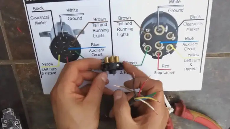
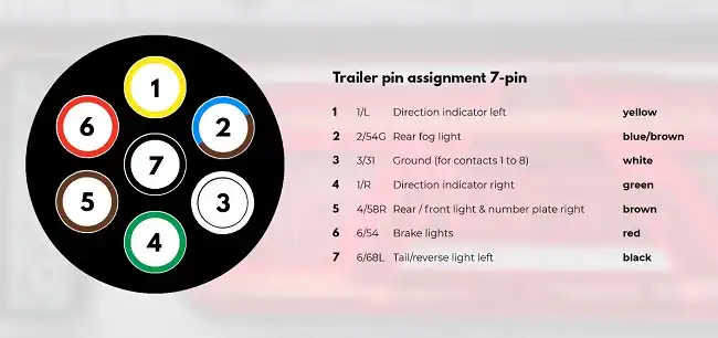
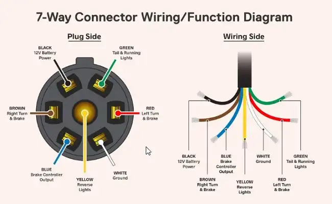
Each of the 7 pins, with associated wiring, carries an electrical signal to activate a separate function. While general standards exist, specifically designated color codes can vary slightly between manufacturers.
The Society of Automotive Engineers (SAE) and the RV Industry Association (RVIA) each have specific wiring standards for proper 7-way plug wiring:
SAE Standard:
- Green: Right turn/brake
- Yellow: Left turn/brake
- Brown: Running lights
- White: Ground
- Blue: Brakes
- Black: 12V battery charge
- Purple: Reverse lights
RV Standard:
- Green: Running lights
- Yellow: Reverse lights
- Brown: Right turn/brake
- White: Ground
- Blue: Brakes
- Black: 12V battery charge
- Red: Left turn/brake
The white and black wires serve as ground connections for the various lighting circuits. Proper pin identification and connections are critical for ensuring all trailer lighting functions correctly. Checking trailer wiring diagrams from the manufacturer prior to connecting is highly recommended.
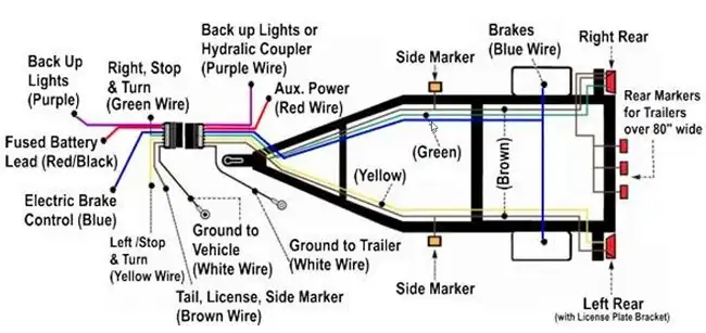
Essential Trailer Wiring Diagrams
There are a number of basic vehicle trailer circuits that wiring harnesses and connectors must carry signals for:
Running Lights: Provides constant power for side marker clearance lights.
Brake Lights: Sends signal to activate trailer brake lights when tow vehicle brakes are applied. Also wired into turn signals.
Auxiliary Power: Extra 12V power line for charging trailer battery, powering accessories.
Reverse Lights: Engages trailer reverse lights when tow vehicle shifter is put into reverse.
Breakaway Switch: Provides charging power to breakaway battery; activated if trailer becomes detached while towing.
Additionally, 7-way connectors allow the integration of electric trailer brake controls, backup cameras, in-vehicle displays, and various auxiliary accessories.
Understanding Trailer Wiring Diagrams
When installing or inspecting 7-way systems, consult the manufacturer’s trailer wiring diagrams to correctly match up wire functions and pins. The diagrams provide specifics on wire gauge sizes, color codes, and circuit ratings to refer to.
Diagrams will also indicate use of multiplexing, which allows a single pin and wire to carry multiple signals, helping reduce complexity.
Steps to Install 7-Way Trailer Wiring
When installing a 7-way trailer wiring system, you will need several materials, including a wiring junction box to house the connections, a breakaway wiring switch, a trailer brake controller if electric trailer brakes are used, and replacement lights or wiring kits if any worn components need replacing.
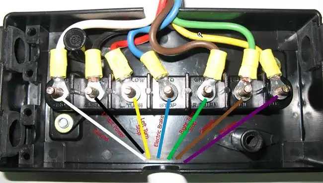
Start by locating an existing junction box, usually mounted near the hitch, and remove the cover to access the wiring studs. If this is a new install, you will need to mount the junction box to the inside of the trailer tongue in an area away from moving parts that could damage the wiring.
To connect the new 7-way harness wires, remove any old trailer wiring completely from the junction box studs, if existing wiring is being replaced. Then, use a crimper to attach ring terminals to the ends of the new wiring harness wires. These ring connectors can be attached to their corresponding junction box wiring studs to join the circuits (ground to ground, brake signal to brake signal, etc.). Use the manufacturer trailer wiring diagram to ensure each wire goes to the proper stud connection. Secure any excess length wiring with wire clips once all connections are made.
If a junction box will not be used, you can cut the ring terminals off and use heat shrink butt connectors to join the new 7-way harness directly to the trailer’s existing wires. Again, follow the wiring diagram to ensure proper wire-to-wire connections. As before, secure any excess harness length with wire clips.
Connecting the Vehicle-Side Wiring
There are a few options for tapping into your vehicle’s power to connect the 7-way trailer wiring.
One simple method is to use a wiring adapter that converts an existing 4-way connector into a 7-way. This plugs right into the 4-flat connector and provides three additional wires that must be connected – one to the electric brake controller, one to the battery hot lead, and one ground.
Certain vehicles come from the factory pre-wired with a plug-in port ready to accept a 7-way trailer wiring harness, usually located by the taillights or rear cargo area. This allows for quick, convenient connection.
Finally, for vehicles without an existing connector, you will need to hardwire splice into the electrical system. This involves manually splicing the harness wires into the matching wires on the vehicle with functions confirmed either through the owner’s manual or using a circuit tester. The connections can be made via crimp splicing, soldering, or quick splice connectors, and the wiring harness should also be grounded to the vehicle frame to avoid dangling.
Once connected on the vehicle side, there are a few options for making the physical wire-to-wire connections: soldering wires together for the strongest bond, applying heat shrink butt connectors for simpler processing, or quick splice connectors for the fastest installation. Be sure to waterproof all electrical connections to avoid corrosion from the elements.
Testing and Troubleshooting Your Connections
Before towing, plug the vehicle and trailer sides of the 7-way wiring together to test operation. Use a circuit tester to check that the turn signals, brake lights, reverse lights, and running lights are all functioning properly. A test light can also be used to confirm each circuit.
Dielectric grease can also be applied to the electrical connections to help prevent corrosion over time from moisture and debris.
If issues occur with the trailer lighting operation, systematically check the following:
- Ground connections on both the trailer and vehicle sides for any loose wiring
- Inspect wires for corrosion, damaged insulation, and severed connectors
- Check fuses in line with lighting circuits for a blown fuse
- Remove and inspect the actual trailer light housings for cracked lenses or broken bulbs
Properly wiring and maintaining 7-way trailer connections takes attention to detail but ensures lighting works as expected for safe travels.
Key Takeaways
Installing and wiring 7-way trailer plugs and connectors properly is critical for reliable lighting and braking while towing. While it may seem complicated, following some key guidelines will ensure everything functions as expected:
- Refer to trailer wiring diagrams to identify each wire’s purpose and make sure all circuits are properly connected
- Use quality splice connections (solder, heat shrink) and verify grounds are solid
- Seal connections completely to prevent corrosion
- Confirm all lights work by testing before hitting the road
- Periodically inspect wiring for damage and apply dielectric grease
Following the steps outlined in this guide and paying close attention to the details of your particular trailer setup will result in many miles of safe, dependable towing. Be sure to consult a professional if you have any questions or run into any wiring problems you can’t resolve.
And with that, you should now have a much better understanding of basic 7-way trailer wiring and installation! Let us know if you have any other questions.