Have you ever stared in confusion at the nest of unmarked wires poking out from your RV thermostat? I certainly have. Making heads or tails of that tangled web gave me headaches when all I wanted was my AC and heat to work. What purpose could the rainbow of nonsensical colors possibly serve other than driving me crazy?
But then it clicked – those wires are color-coded, and with the right diagram, they transform into a treasure map marking the way to wiring success. Once I matched red to R, white to W, and so on at the terminals, suddenly I held the power at my fingertips (literally) to get my climate control functioning flawlessly. In minutes I went from staring at spaghetti to staring proudly at my operational thermostat!
So let me grab you by those puzzle-piece wires and guide you through solving the mystery to get your RV comforts running smoothly. Just remember – a wiring diagram makes even the most Gordian mess of cables as easy as 1, 2, and green! Read on!

Importance of Using a Wiring Diagram
You may be wondering if it’s worth your time and brainpower to decode the wiring schematic. After all, can’t you just connect the wires however they fit? I urge you NOT to take shortcuts when it comes to RV electrical systems. Improper wiring can lead to device malfunction, power shorts, fires, and other disasters you want to avoid at all costs.
Trust me when I say investing the effort upfront to understand the wiring diagram will pay major dividends down the road in enjoying uninterrupted climate control and safety for you and your family. Once you grasp the basic color coding and terminal functions, it will all start to make sense.
Main Components of a 4-Wire RV Thermostat
Most RV thermostats have 4 wires to connect, each color-coded for easy identification. Here is what each wire controls:
The key elements section covers the 3 main components that you need to understand in a basic RV 4-wire thermostat wiring diagram. These critical pieces are:
Color-coded Wires
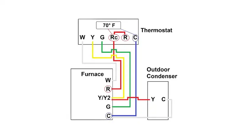
The diagram shows each wire labeled with a specific color that represents its function. These colors are:
Red wire (R) = Provides 12V power
Green wire (G) = Activates AC fan
White wire (W) = Completes the circuit
Yellow wire (Y) = Turns on the AC compressor
Knowing the color associations is crucial for properly matching up terminals later. Mixing up wire colors can cause serious problems.
Wire connections
The wiring diagram traces exactly where and how each color wire should be connected for thermostat operation.
A good wiring diagram illustrates exactly where each colored wire should connect:
- The thermostat
- The RV’s 12V power supply
- The HVAC system (heating, ventilation, and air conditioning)
you need to link them together using that wire’s matching color.
Terminal Labels
Finally, the wiring diagram shows what letter codes and labels exist on the terminals for each component – the thermostat, power source, HVAC board, etc. These letters (R, G, W, Y) must match up to the associated wire color that you connect to that terminal. Matching wire colors AND terminal labels prevents any incorrect wiring.
In summary, those 3 elements – color-coded wires, connection points traced between components, and terminal identification codes – provide the complete picture of how to properly install the 4-core thermostat wires to enable safe control of the RV’s heating and cooling system.
Step-by-Step Guide to Connecting a 4-Wire RV Thermostat
Connecting a 4-wire RV thermostat requires securing each color-coded wire between the thermostat unit, the vehicle power supply, and the heating and cooling equipment. Let’s go through the process:
Step 1) Find the Red Power Wire on the thermostat labeled ‘R’.
Run this wire to the distribution panel and join it to a 12V power supply circuit that is always live. Use wire nuts or crimp connectors to firmly attach the wires. This provides electricity to operate the thermostat controls.
Step 2) Locate the Green Fan Control Wire on the thermostat marked ‘G’.
Connect this wire securely to the RV AC unit’s internal fan motor or circuit board terminal labeled Fan. This enables the thermostat to switch the fan on and off to circulate conditioned air.
Step 3) Next identify the Yellow Compressor Control Wire on the thermostat labeled ‘Y.’
Run this wire directly to the AC compressor’s activate terminal. When 24 volts is sent on the yellow wire, it signals the compressor to turn on and energize the coils to provide cooling.
Step 4) Finally, find the White Neutral Return Wire at the ‘W’ terminal on the thermostat.
Connect this to the common neutral bus bar in the distribution panel, completing the circuit for the current to flow. The same panel where you sourced 12V power.
Those 4 simple yet vital connections enable full smart temperature control from the central thermostat panel. Just be 100% certain to connect wire colors to the matching labels on both the thermostat and heating/cooling units it operates.
Benefits of Following the Wiring Diagram
I know what you may be thinking: “What’s the worst that could happen if I connect the wires randomly without the diagram?” Well, let me emphasize why adhering to the schematic matters:
Ensures Proper Thermostat Installation
Connecting the right wires in the right sequence allows your thermostat to operate as designed by the manufacturer. You want to avoid improvising connections on such a vital system.
Facilitates Safe & Accurate Wiring
Thermostat wiring diagrams incorporate safety features that prevent potentially hazardous conditions from developing. For instance, separating high and low-voltage wires avoids shorts.
Enables System Control
Finally, the main motivation for wiring the thermostat correctly is control. Following the diagram allows your thermostat to reliably and accurately govern the RV’s heating, cooling, ventilation, and other functions that enable comfortable indoor temperatures in your living space, regardless of the weather outside.
So in summary – safety, control, and avoiding headaches down the road all require investing a bit of time to properly interpret the wiring diagram for your particular RV thermostat.
Wiring Options for Different RV Thermostat Types
While I’ve focused on 4-wire diagrams, it’s important to note thermostats come in different configurations for various RV models. Let’s look at other common options:
Single Stage 12V DC Thermostat
Here is a typical wiring schematic for a simple, single-stage DC thermostat in a camper:
| Color | Code | Function |
| Green | GH | High-Speed Operation for the Fan |
| Yellow | Y | Activates the AC Compressor |
| Red | R | Positive Terminal (+12V DC) |
| White/Black | WhB | Controls the Heat Pump |
| Gray | GL | Low-Speed Operation for the Fan |
| Blue | B | Negative Terminal (-12V DC) |
| White | WF | Initiates the Furnace |
This provides individual wire control over cooling and heating systems.
2-Stage 12V DC Thermostat
Larger RVs may incorporate a 2-stage thermostat capable of both high and low output depending on temperature demand:
| Connector | Color | Code | Function |
| Main Connector | Gray | G | Second Terminal for Freeze |
| Yellow | Y | 1st AC Compressor Terminal | |
| Red | R | Power Supply (12V DC Power) | |
| White/Black | WhB | Electric Heater Control | |
| Gray | G | High Setting for Air Conditioning | |
| Black | B | Negative Terminal (-12V DC) | |
| Purple | P | Indoor Fan Low Speed | |
| Blue | B | Negative Terminal | |
| Orange | O | AC Compressor Terminal 2 | |
| Second Connector | Red/White | RWh | Positive Power supply (+12V DC) |
| Blue/White | BWh | Negative Power supply (-12V DC) | |
| White | Wh | Low Setting for RV Heat Pump | |
| Orange/White | OWh | High Setting for RV Heat Pump |
Analog Thermostat
| Color | Function of 12V Power | Function of 24 Volt |
| Green | Controls High-Speed Operation of the Fan | Controls Fan Output for Auto-On |
| Gray | Manages Low-Speed Operation of the Fan | N/A |
| White | Governs the Heating Element | Manages Heat Output |
| Yellow | Activates AC Compressor for Cool Settings | Manages AC Compressor Output |
| Red | Connects to Positive Terminal (+12V DC) | Manages Cool Settings |
| Blue | Connects to Negative Terminal (-12V DC) | N/A |
| Red/White | N/A | 24V Input for Heat Control |
The key addition is a second stage of heating for colder conditions, ensuring the RV interior warms up quickly and evenly.
As you can see, RV thermostat wiring can vary across models, so be sure to find the correct diagram for your specific camper or trailer. Understanding these configurations will pay dividends in ease of use, safety, and comfort during your RV adventures!
Conclusion
I hope this all-encompassing guide has helped eliminate any confusion surrounding RV thermostat wiring. While it may seem intimidating at first glance, the color coding and labeling conventions are there to guide you in making the proper connections.
The most important takeaway is: to invest the initial effort into deciphering the wiring diagram for your particular RV. This will prevent improper installation that could render the climate control system inoperative. And you definitely want to keep things like air conditioning and heat working properly in an RV!
Feel free to drop any additional questions in the comments section below. And don’t hesitate to consult your owner’s manual or an electrician if you have any doubts about the wiring process. The goal is to stay comfortable in your RV through safe, reliable climate control you can count on. Thanks for reading – now go connect those thermostats like a pro! Travel safe out there!


